Below is a diagram of a basic process transmission probe with all of the key elements illustrated. However any
specific probe may vary significantly in layout and implementation.
Anatomy of Fiber Optic Probe
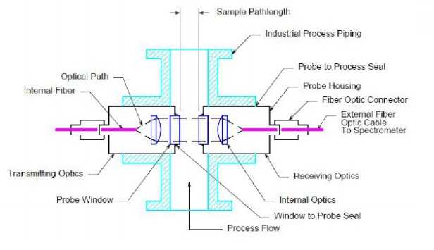
- The outer hatched BLUE area represents the industrial process. For laboratory applications, a cuvette or other experimental apparatus would replace the process plumbing.
- The probe is contained in a housing that must be sealed to the process to prevent escape of the sample. The housing is usually metallic but may be glass, ceramic, polytetrafluoroethylene (PTFE), polymer or any material compatible with the process.
- The probe-to-process seal may be o-rings, energized seals, compression fittings, chevron seals, welded flanges, etc. The process owner will specify the seal depending on the process parameters and safety requirements.
- Light is brought to the probe via a fiber optic cable, which is connected to the probe by means of an optical connector. Several types of connectors are typically used including SMA, FC, and ST connectors.
- Internal to the probe, the light may be conducted to the vicinity of the process via another fiber optic cable that is terminated in a collimating lens. The collimated light is then directed through a window to a similar configuration on the other side of the process sample. The receiving optics then image the light into the return fiber which conducts the light not absorbed by the sample back to the spectrometer or photometer.
- The optical window that separates the process from the internal optics of the probe must be sealed to the probe in a process compatible manner. This seal may again be an o-ring or similar polymer seal, a glass-to-metal braze, or other technologies depending upon the materials involved and the process requirements.
- Note that the separation of the windows defines the optical pathlength of the probe. Precise knowledge and/ or repeatability of this pathlength are often critical for accurate quantitative spectroscopy. Modern NIR spectrometers are capable of signal-to-noise ratios exceeding 105:1. Quantitative measurements are, therefore, often limited by othe repatability of the pathlength of the probe.
Common Materials Used
Common optical materials for ultraviolet (UV), visible (VIS), near-infrared (NIR) and (FT-NIR) probes are fused silica, sapphire, and borosilicate crown glass (BK7). Other common glasses may also be used.
| WINDOW MATERIALS | TRANSMISSION (nm) | PROS | CONSIDERATIONS |
| Fused Silica (FS) | 190 – 800 nm | – Low optical dispersion – Low index of refraction | – NIR requires Low-OH content fiber – UV and (<500 nm) wavelengths require High-OH content fiber |
| Sapphire | 190 – 5500 nm | – Free of absorption feature – Extremely hard – High index of refraction | For lenses, high refraction is an advantage since spherical aberration is reduced |
| Borosilicate Crown Glass (BK7) | 380 – 2100 nm | – Lower cost than other materials – Available in a wide variety of sizes and focal lengths | Softer than fused silica or sapphire so not good for harsh applications |
Fused Silica
Fused silica transmits from 180 nm to 3000 nm with varying absorption bands depending on the water or OH content. It has relatively low optical dispersion, is hard and has a low Fresnel reflection coefficient (low index of refraction). Virtually all the optical fibers used in the UV, Vis, and NIR regions (200 – 2200 nm) are made from ultra-pure fused silica rods with a fluorine doped fused silica cladding. Low-OH content fiber is required for NIR applications, while high-OH content fiber performs better in the UV and short wavelength (<500 nm) visible region.
Sapphire
Sapphire transmits from 150 nm to 5500 nm, is free of absorption features, and is extremely hard. Sapphire has a relatively high index of refraction, hence a larger Fresnel reflection coefficient than glass or fused silica. For lenses, this is an advantage since spherical aberration is reduced.
Borosilicate Crown Glass (BK7)
BK7 works well from 380 nm to 2100 nm. It is significantly softer than fused silica or sapphire, hence does not make a good window material for harsh applications. However, BK7 lenses are inexpensive and available in a wide variety of sizes and focal lengths.
Differences Between Probes and Flow Cells for FT-NIR, NIR and UV-VIS
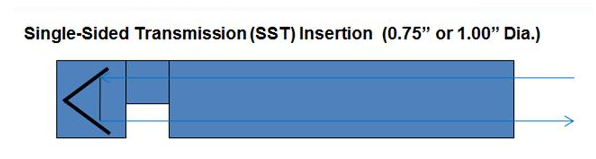
- Single pass through the sample
- Optical path = physical gap
- Best for small paths (1,2 mm)
- Brazed or o-ring windows seals
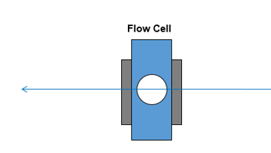
- Single pass through the sample
- Optical path = physical gap
- Accommodates small paths (1mm)
- O-ring window seals (lower transmission)
- Can be made from Teflon for corrosion resistance
Over a quarter century ago, process probes for fiber optic spectroscopy were small, fragile devices with poor optical throughput, ill-defined path lengths and uncollimated light beams. Guided Wave pioneered in-line fiber optic sample probes more than two decades ago, with the introduction of the SST (Single Sided Transmission) Probe. (Figure A above) These types of probes permit precise spectroscopic analysis of products directly in the process line without the need for sample systems and their associated investment and installation costs, lag times, failures, and constant maintenance requirements.
The SST Probe eliminates the need for complex sampling systems with their expense, maintenance, and lag times. By installing an SST probe in-line (in situ) in a pipe or reactor through a single access port, the process is directly monitored and measured without altering the substances being monitored.
Insertion probes can be directly dipped into a laboratory beaker or inserted into a process pipe, so that the light is truly brought to the sample. However, in some applications, it may be more convenient to compromise and meet the sample halfway by using a flow cell. When it is not possible to insert a probe directly into a process line due to safety reasons, service requirements or the need to precondition the sample, a flow cell is the best choice.
While an insertion probe approach can often reduce installation costs, sometimes safety, servicing, and/or sample conditioning requirements make it necessary to integrate a sampling loop or slip stream. (Figure B above)
Flow cells are preferred whenever:
- Direct insertion probes are inappropriate
- Required optical path length is 30 mm or greater
Probe and Flow Cell Maintenance – Consider Usability
No matter the manufacturer all probes and flow cells used for absorption spectroscopy must be referenced periodically. The period will depend upon the instrument and the process and may range from weeks to several months. Furthermore, the windows may need periodic cleaning, plus o-rings and other elements may need service.
Therefore, practical methods for removal of the probe and flow cell from the process, access to the windows, or complete disassembly and reassembly abilities are often desirable features to look for when choosing new sample interfaces. Some companies offer probe extraction devices and/or cleaning ports on flow cells to facilitate this maintenance.
In order to distinguish differences between probe or analyzer issues some analyzers have onboard diagnostic indicators and can be equipped with a stability monitoring system